This is part of a series of articles about how one could design a data-centre network, concentrating on Ethernet, although some details can be used for Infiniband or other technologies as well.
- Non-blocking DC network
- Using BGP between hosts and switches
- Achieving leaf redundancy by multi-homing hosts
- Supporting network boot
In this first installment, we will look at a way to organize hosts and switches to support networks of practically arbitrary size. To make things easy, I will only show 4-port switches in the examples; in a real setup, you would use larger switches.
We start with a single switch:
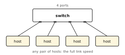
We can attach up to four hosts; these hosts will be able to reach each other and usually will be able to fully load their single connection1.
How to add more hosts?
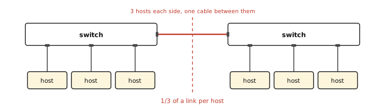
Now we can have up to six hosts: each switch spends one of its four ports on the cable to the other one. But if the hosts on the left switch need to communicate with the hosts on the right switch, they will hit that single connection as a bottleneck.
This is what the bisection bandwidth measures: cut the network into two halves with the same number of hosts in each, add up the bandwidth of the cables you had to cut, and take the worst such cut you can find. Here there is only one place to cut, it crosses one cable, and three hosts on each side have to share it — so 1/3 of a link per host.
This will only get worse if you add more switches:
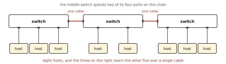
Three switches give us eight hosts rather than nine, because the switch in the middle has to spend two of its four ports on the chain. And the chain has not become any wider: the three hosts on the right still reach the other five over a single cable. Every switch you add costs you ports and buys you no bandwidth in the middle.
Some switches have an “uplink” port with a higher bandwidth (e.g., 10 Gbit/s for a 1 Gbit/s switch), but that can only get you so far — it moves the bottleneck, it does not remove it.
The solution is to build a Clos network2. You will begin by using half the ports of a switch to connect to the hosts (2 in our small example), and the other half you use to connect to so-called “spine” switches. The switches connected to the hosts are called leaves.
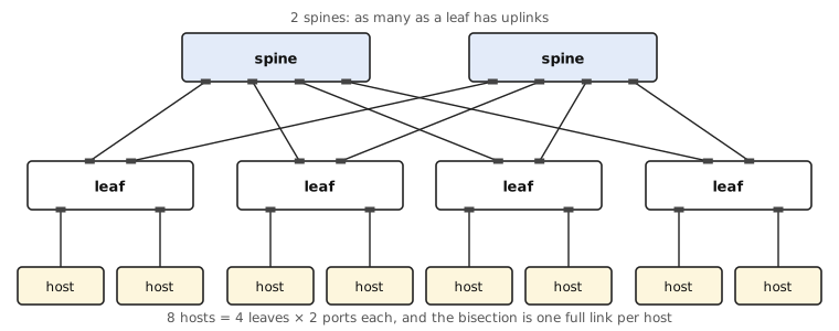
Two things fall out of that picture, and both of them are the whole trick:
- A leaf has two uplinks, so there are exactly two spines. The number of uplinks per leaf is the number of spines, because every leaf goes to every spine exactly once.
- A spine has four ports, so it reaches four leaves, and four leaves with two host ports each give us eight hosts.
In general, with switches that have k ports, you get k/2 spines, k leaves and k²/2 hosts. Our toy example is 8; with the 32-port switches you would actually buy it is 512, and with 64 ports it is 2048. When you run out, you add a third tier of switches on top of the spines and repeat the trick, which gets you to k³/4 — 8192 hosts out of nothing but 32-port switches. That is what “practically arbitrary size” means here: the topology scales by adding tiers, and every tier is built out of the same boring switch.
If your switches have ports of different speeds or if they support breaking out a port into multiple slower ports, you do not need the same number of links “up” and “down” — but you do need the same total bandwidth. For example, if you have an 8-port 100 Gbit/s switch that allows breaking out a port into 4×25 Gbit/s, you can use four ports as 16×25 Gbit/s to the hosts and the remaining 4×100 Gbit/s to the spines. 400 Gbit/s down, 400 Gbit/s up.
Nobody makes you keep that balance, and plenty of people deliberately do not: running 2:1 or 3:1 more bandwidth down than up is called oversubscription, and it is a perfectly reasonable thing to buy if you know your hosts do not all talk at once. It is only worth doing on purpose, though. Oversubscription you discover during an incident is just a bottleneck with a nicer name.
It is, and that is the next problem. A broadcast packet sent by a host will be sent to both spine switches that will send it to all leaf switches that will send it back to both spine switches, … You could use a spanning tree protocol, but that will turn off links until it reaches a loop-free state — which is exactly the opposite of what we bought all those cables for.
The best solution is to stop doing Ethernet in the middle: configure the switches as routers (which all big modern switches can do) and break up the broadcast domains, so that a leaf is its own little network and the fabric above it is routed. The leaf switches then need to be configured to use both spine switches to reach the hosts on another leaf. That is ECMP (equal-cost multi-path): the router hashes something stable about each flow — usually the IP addresses, protocol and ports — and picks a next hop from that hash, so that the packets of one connection all take the same path and do not arrive out of order. How the leaves learn all those routes is the subject of the next installment.
You can easily assure yourself that the fabric in that picture can now run at full capacity between all hosts: the bisection bandwidth per host is the same as the link speed between host and switch. That is the “non-blocking” in the title — the network in the middle is never the reason you are slow, only your own cable is.
With one asterisk, and it is the one everybody trips over: ECMP hashes, it does not schedule. Two large flows can land on the same leaf-spine link while the other one sits idle, and the hash has no idea. The capacity is there; the load balancing is statistical3.
A neat trick you can do is double up links between leaf and spine if you want to save rack space and money:
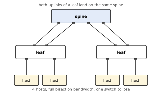
This way, you get the full bisection bandwidth for a smaller network. In our example this is nonsensical, as we can then only have as many hosts as one switch supports — and we have bought a single point of failure to go with them. But with larger switches, and a second spine added the day the first one is not enough, this is a normal way to start.
- Only usually, because that is a property of the switch, not of the picture: it needs a switching fabric that can carry all ports at line rate at the same time. Anything you would put in a rack has one; the switch built into your ISP’s router quite possibly does not. ↩︎
- After Charles Clos, who described the idea in 1953 for telephone exchanges, in a paper with the wonderfully blunt title “A Study of Non-Blocking Switching Networks”. The same shape was rediscovered for computers as the fat-tree, and brought to data centres by Al-Fares, Loukissas and Vahdat in 2008 — which is roughly when every vendor’s marketing department learned the word “spine”. ↩︎
- Clos’s original theorem is about circuit switching, where you can prove a network is non-blocking. A packet fabric borrows the topology, not the proof. If the collisions actually hurt you, the escalation path is flowlet-based balancing, adaptive routing, or per-packet spraying with reordering handled at the endpoint — all of which are much easier to buy than to reason about. ↩︎
Comments
With an account on the Fediverse or Mastodon, you can respond to this post. Since Mastodon is decentralized, you can use your existing account hosted by another Mastodon server or compatible platform if you don't have an account on this one. Known non-private replies are displayed below.
Learn how this is implemented here.